| My own floppy interface
( MZ-700 / Commodore 1571 )
|
|||||||||||||||
| Introduction | |||||||||||||||
|
There were a Commodore C64 and a floppy drive 1571 available at my site. This drive has its own system program and so it was easily to handle for programming. The 1571 has only a serial bus and the data transfer is not very fast, but it is faster than the data recorder MZ-1T01. This should become my floppy station for my MZ-731, but you can use the 1541, 1570, or 1571 floppy drive too. I can't connect the 1571 directly to the expansion bus and additional hardware should be very simple at first. The hardware is very simple, however, maybe, not for those who never had soldered any electronics components on a printed circuit board or a grid board. If that is the case you should not attempt it. Think, your MZ-700 can be destroyed if you do anything wrong. In that case it would be advisable to get help from someone experienced in soldering electronic components. To produce a printed circuit board you need help too. I can't explain here the complex production. Electronics shops may be able to help you further or they might even be able to supply you with the PCB ( Printed Circuit Board ). At first I will discuss the simple hardware and next the software. The software, its source code, and the documentation is available here for download. |
|||||||||||||||
|
|||||||||||||||
The minimum amount of physical lines to the 1571 needed are the lines ATN, CLK, DATA and GND. For communication these lines must be bi-directional, that means, each line must be able to be an input line at a time and an output line at another time. The 8255 of the MZ-700 has three unused output lines which I use. There are no more unused lines available for the three input lines needed. I use three lines of the joysticks for this. In effect by this, you can use the joysticks, but you cannot use the joysticks during floppy access. Doesn't matter, I think. To this, see the diagram needed for the interface: 
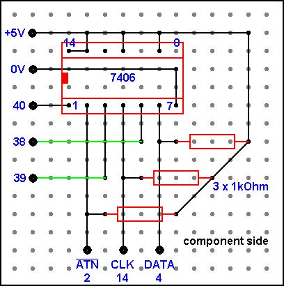
PA4, PA5, and PA6 are the three unused output lines of the MZ-700. JA1, JA2, and JB1 are the joystick inputs I use for my purpose. The numbers of the IC's, 4C and 8E, are the part numbers labeled on the component side of the MZ-700's motherboard. The hardware of my interface contains one IC ( Integrated Circuit ) type 7406 and three resistance of 1 KOhm to pull up the input lines to a logical 1 ( +5 Volts ). The 7406 contains 6 identical inverters, three of them will be used by this interface. The logical output value of an inverter will be the opposite value of its logical input. I've set the IC into a socket with 14 pins that is soldered on the component side of the PCB, but you can carefully solder the IC directly onto the PCB. You need a female plug like this too: 
The same one is installed in the C64 and the floppy drive. You can try to find a place for mounting the plug at the reverse side of your MZ-700 or, well, not the best solution, you install a long cable having mounted a plug with housing at the end of the cable coming out anywhere of the reverse side of the MZ-700. You can solder all components on a PCB like this: 
PCB's are laminates. This means that they are made from two or more sheets of material stuck together; often copper and fiberglass. Components will be on one side of the board, soldered joints the other. This PCB is copper clad on one side only and this side, the soldering side, looks like this: 
The size of the PCB is 46 mm x 33 mm. Components are to stuff into the board and next to be soldered at the red donut pads having a drilled whole of 0,8mm diameter in the middle of it. Fit components so that they lie flat on the board. Solder two diagonally opposite pins on the socket for the IC 7406 and check them for flatness before soldering the rest. Cut off excess leads but do not cut the solder. There is another way, if you don't want to produce a PCB for this simple hardware. You can solder all components on a Grid Board. A Grid Board is pre patterned pad-per-hole designed, pre punched, and this one has a grid spacing ( a hole pitch ) of 2,54mm ( 0.098" - 0.1" ). A Grid Board doesn't have like a PCB copper tracks. Instead of the copper tracks of a PCB you have to solder non isolated, silver plated wires between all leads of the components to get all the connections needed.
Do the same procedure for the ends of the wires of the 3 resistances.
Again, solder two diagonally opposite pins on the socket for the IC
and check them for flatness before soldering the rest. Cut off excess
leads but do not cut the solder. The labeled black donut pads are to
be connected with the IC's on the motherboard of the MZ-700 and with
the plug. To this, a detailed description follows later in this section.

When the board is ready you have to connect the labeled pads. The numbered pads 38, 39, and 40 are to be wired to the IC# 8E, the 8255, on the motherboard of your MZ-700. To this find out the 8255 on the motherboard and pay attention to the mark of the IC and the numerical order in association with the mark of the IC. Think, the numerical order goes vice versa when you see the soldering side. Sketch the pins if you are not well trained in the numerical order of IC's. Solder the 3 wires at the pins 38, 39, and 40 of the 8255 on the soldering side of the motherboard. Do the same for the 3 wires to the IC# 4C ( LS367 ) and solder them at the pins 2, 4, and 14 as shown on the grid board and the diagram above. Again, pay attention to the numerical order. You can get a pinout description of the 8255 here ( seen from the component side ). If all components are soldered, set the IC 7406 into its socket. Now you have to solder 3 wires to the plug. The following table shows the connections to do:
Now you have to mount your board on the motherboard. I have mounted it "cantilever" between IC#6C and IC#8C on the motherboard's component side. For this I've soldered to the +5V pad from the soldering side a thick 1mm wire and soldered it to the thick +5V track going between IC#6C ( 74LS32, 14 pins ) and IC#7A ( M60719, 60 pins ) on the MZ-700's motherboard. I've also soldered to the 0V pad a thick 1mm wire and soldered this to a Ground track on the motherboard near to my tiny board. The thick wires will hold the tiny PCB / Grid Board on the motherboard. Pin 2 of the plug must be soldered too to a Ground track near to the
plug. That's it and you can re-assemble your MZ-700 now. Then try to
start your MZ-700, connect the floppy drive and load the following software.
|
|||||||||||||||
| The software | |||||||||||||||
|
The following functions are available by this version of the software:
This version is unable to Save / Load a BASIC program. You can start the program by JA000 from the monitor's prompt. The program is loaded into the memory from $A000 to $AB3F. When the program is started you get the following short prompt:
LSVCDIPF : Each character is the short form of a command. At the end of each process the program tries to get and display the drive status message, for example, 00, OK,00,00. A description of the commands follows now. |
|||||||||||||||
|
LSVCDIPF: L Searching for MYFILE MYFILE is the file name of the file to be loaded. C000 is displayed
by the program. C000 is the address typed in during the save process
as the start address of the area to be saved. You can change the address
if the data is to be loaded to a new location. |
|||||||||||||||
|
LSVCDIPF: S Begin : C000 The name of the file to be saved is MYFILE, for example. The data
to be saved is located in the memory from $C000 to $CA94. |
|||||||||||||||
|
LSVCDIPF: V Depending on possible write errors during a save or depending on a damaged disk the following messages are possible: LSVCDIPF: V In this case take a new disk and save the file again. |
|||||||||||||||
|
LSVCDIPF: C This example shows the mode change of the 1571 from the 1541 mode to
the 1571 mode. |
|||||||||||||||
|
LSVCDIPF: D The first 3 messages will be overwritten by the directory display
that follows. |
|||||||||||||||
|
If the screen is full no key action is needed as needed for the "D" command. The program waits until the last character on the screen is printed and then automatically displays the next screen. The current character printed is inverted on the screen to see the
progress of the print output. |
|||||||||||||||
|
LSVCDIPF: F Another example is: LSVCDIPF: F |
|||||||||||||||
|
This version stores only the start address of a file in the first two
bytes of each file. |