| SUC RGB Colour Card
written by G. Jones / SUC/UK
Source: SUC-magazine December 1983, Volume 3 Number 4, pp. 26 - 28 |
||||||||||||||||||||||||||||||||||||||||||||||||||||||||||||||||||||||||||||||
| SHARP COLOUR CONVERSION | ||||||||||||||||||||||||||||||||||||||||||||||||||||||||||||||||||||||||||||||
|
I am also building an EPROM programmer that plugs into the Sharp I/0 box. As you can see I'm interested in hardware and would like to get in touch with like-minded members. Software-wise I'm interested mostly in m/c + assembler and have a MONITOR SOURCE file under ZEN which can be assembled anywhere - in RAM and thus be modified and examined in detail; this source file is heavily commented. I also have a source file for ZEN-DOS, ZEN, and a home made DISASSEMBLER. ZEN-DOS is an absolute must for any serious disk work as the utilities allow almost anything to be done to any disk and can load 16K programs from disk in about 3 or 4 seconds.
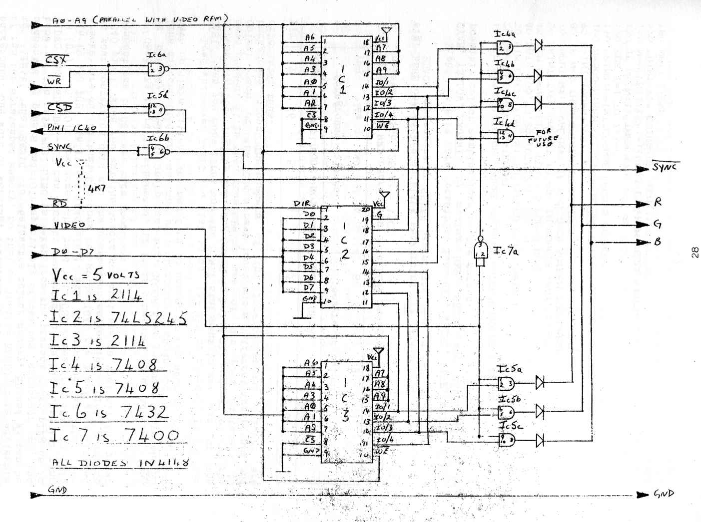
The circuit diagram shows how to convert your MZ80K to colour for about £5.00 worth of chips. The circuit as shown gives RED-GREEN-BLUE output suitable for driving a monitor; if you wish to use it on a television a UHF colour modulator is available from ASTEC at 4A Sheet St., Windsor, Berks ( 07535 ) 55245, which accepts RGB inputs and converts them to signals suitable for a domestic TV: the modulator number is UM 4101. IC's 1 and 3 are 4 bit static rams x 1024 which allows you to store one 8 bit number for each location. reading and writing to those rams is via IC2. This 8-bit number is split into 4 upper and 4 lower bits to give RGB for foreground and background colours. This is achieved by 'ANDing' the 'video' signal with RGB outputs. The diodes must be fairly fast diodes: 1N914's or 1N4148's are acceptable otherwise horizontal lines will be lost on the screen. The 'sync' signal is inverted because it suits my monitor but this can be changed by omitting IC6b. This board requires direct soldering to the main PCB and leads should be kept as short as possible. Address lines A0 - A9 are connected directly to the pins of the video ram IC41 and IC42 in the following manner:-
CSC and CSX are connected to IC47 on the pins shown above. CSX is the connection that decides the address of the colour ram. This is to make it easy for software purposes, e.g. if CSC is used then the addresses of the colours would be from 49152 to 50151 so that the command POKE 50151, X would change the colour of the last square on the screen to whatever colour you choose for foreground and background. One word of warning, different BASIC's' use different pages of ram for scratchpad memory, so that on loading BASIC it is advisable to 'limit' the BASIC to below the colour memory. RD and WR can be connected to pins 8 and 10 respectively of the bus connector at the back of the main PCB. SYNC is taken from the present video plug as is VIDEO and GND. D0 - D7 can also be connected to the bus connector pins 18 ( D7 ) - 25 ( D0 ). Now comes the hard bit. CSD comes from IC47 to IC43 pin 19 and IC23 pin 11 and IC40 pin 1. What is required is that the tracks are cut so that CSD does not go to IC40 pin 1 but goes instead to your conversion card and the connection marked IC40 pin1 goes to IC40 pin 1. When you cut the tracks you must ensure that all the other connections to CSD are made good. Once the board is connected, if it is connected to an address that is already used by Sharp ram, e.g. C000H then you must leave the RD line disconnected and use the pull up resistor shown dotted. If you have no disks fitted, you may find it easier to use address F000H. Load whichever BASIC you wish to use ( or ZEN or m/code ). If you use BASIC then you must first use the LIMIT statement to get rid of the screen 'glittering' by limiting BASIC to below the address of ram you have chosen. It is then possible by use of the POKE statement to colour each of the 1024 screen locations a different foreground and background colour. The numbers of the fore/background colours are calculated thus.
e.g. e.g. Eight colours are possible, i.e. RED, GREEN, BLUE, WHITE, BLACK, CYAN, YELLOW, MAGENTA by mixing RED, GREEN and BLUE, giving 64 possible colour combinations on the screen. 10 REM SIMULATION OF CHANGE MACHINE WHICH HANDLES 7 COINS |
||||||||||||||||||||||||||||||||||||||||||||||||||||||||||||||||||||||||||||||