| Disks in detail
written by Tim Cowell / SUC/UK
Source: SUC-magazine December 1986, Volume 6, Number 2, pp. 44 - 48 |
|||||||||||||||||||||||||||||||||||||||||||||||||||||||||||
|
Sharp Users Club - MZ-700 Section - Disks in detail |
|||||||||||||||||||||||||||||||||||||||||||||||||||||||||||
|
My objective was to get a disk system for my MZ700 without spending
the vast amounts of money usually required for such nice things. I wanted
my disk system to be compatible with existing disk systems but to also
provide a more comprehensive operating environment. |
|||||||||||||||||||||||||||||||||||||||||||||||||||||||||||
|
The Hardware |
|||||||||||||||||||||||||||||||||||||||||||||||||||||||||||
|
|
|||||||||||||||||||||||||||||||||||||||||||||||||||||||||||
|
The Software |
|||||||||||||||||||||||||||||||||||||||||||||||||||||||||||
|
The interesting thing to note is that all disk accesses are done by reference to the logical sector numbers. Each disk is double sided, 35 tracks per side and 16 sectors per track. To convert a logical sector into physical side, track & sector the following calculation should be done :-
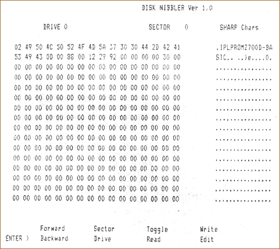
In practice however the software assumes it is a 70 track drive and automatically splits the track number ( 0 to 69 ) into track and side when accessing the disks. The bootstrap ROM lives at F000H, when you type 'F' from the monitor, the processor looks at F000 and if it sees a ROM there then jumps to F000. This displays a prompt asking for the boot drive, press 1 to 4 or simply [CR] to default to 1. The system then reads in logical sector 0 to memory at CE00 ( 256 bytes ). If it is a boot disk this sector will contain a header with a file name beginning with “IPLPRO", a new memory load address, the size of the file and the start sector on disk. This is then loaded and run, the disk I had was the Disk Basic disk. All the routines in the ROM get their parameters from memory pointed to by the IX register, this is usually set to 1008H. It is possible to use these ROM routines yourself by setting up a parameter block and calling them, however I am not sure that all versions of the boot ROMs contain the same code. To read sectors from disk into memory the following technique was used,
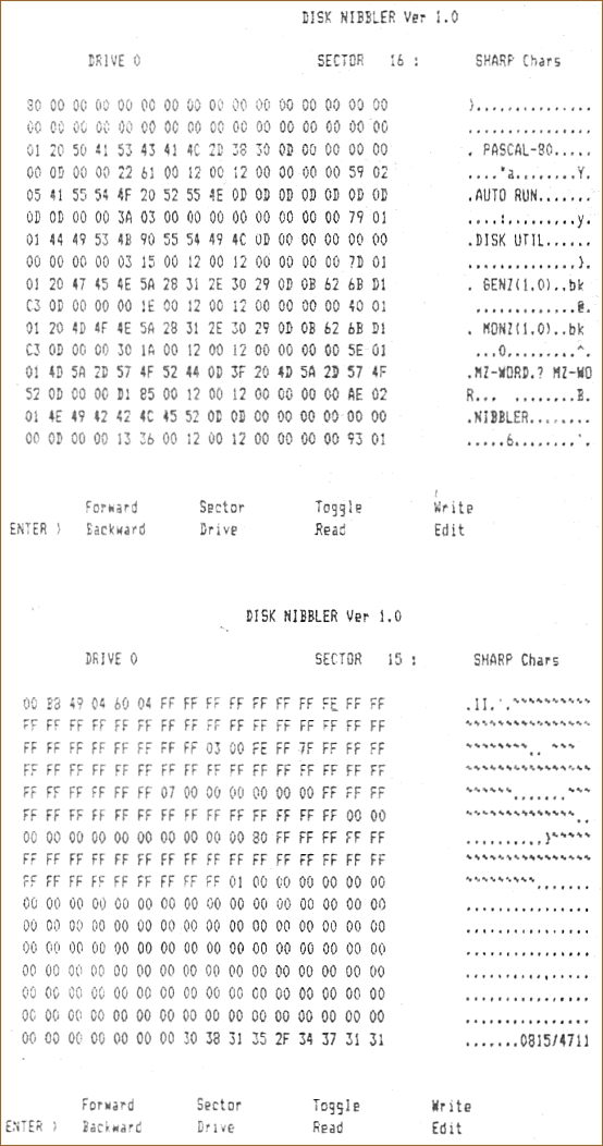
Using the above technique I was able to write a small MC program to read disks sector by sector and display their contents in Hex and ASCII form. The following are printer dumps of the results :-
Analysis of the above for various disks enabled me to determine how the system uses various sectors. Sector 0 = Boot information sector. |
|||||||||||||||||||||||||||||||||||||||||||||||||||||||||||
|
Sector 15 |
|||||||||||||||||||||||||||||||||||||||||||||||||||||||||||
|
|
|||||||||||||||||||||||||||||||||||||||||||||||||||||||||||
|
Sectors 16 to 23 |
|||||||||||||||||||||||||||||||||||||||||||||||||||||||||||
|
|
|||||||||||||||||||||||||||||||||||||||||||||||||||||||||||
|
Sectors 0 |
|||||||||||||||||||||||||||||||||||||||||||||||||||||||||||
|
|
|||||||||||||||||||||||||||||||||||||||||||||||||||||||||||
|
The Kersten & Partner System |
|||||||||||||||||||||||||||||||||||||||||||||||||||||||||||
|
1) Load the utility in the usual way and press the reset button. 13B9 20 18 [CR] ( You enter the 18 and CR ) The disk copy option will now copy anything. There is also what I consider to be a bug in the Disk Basic. There is a utility which allows machine code programs to be loaded from tape and saved to disk, these can then be executed from disk basic. However certain programs refused to run properly, on investigation I found it was programs using any of the monitor melody routines including the beep. In fact it was because Disk Basic changes the TEMPO byte at 119E, this causes all sound routines to take much longer to execute. A simple solution is to modify disk basic as soon as it loads by including the following two lines as part of your ‘AUTO RUN‘ program. 1 RESTORE : FOR I = 0 TO 4 : READ D : POKE $7AB3 + I, D : NEXT This simply causes the original value of 04 to be restored before the
interpreter jumps off to execute a loaded machine code program. |
|||||||||||||||||||||||||||||||||||||||||||||||||||||||||||
|
What Next |
|||||||||||||||||||||||||||||||||||||||||||||||||||||||||||
|
My intention is to use these to produce a BIOS / BDOS for a simple
operating system which is to be tape compatible. The directory read
/ write and file load / save routines are compatible with the inbuilt
tape system. Each time a header is loaded the software effectively reads
the 'Next' directory entry into the tape header area of memory. The
disk is therefore treated as a tape with many files, except access is
direct as the directory points to the location of the files on disk.
Any help or constructive comment concerning a simple DOS would be most
welcome, also I am considering making a PCB of the controller interface,
if anyone has a PCB design package or access to one and feels they could
have a go then write to me and I will supply the circuit diagram. |
|||||||||||||||||||||||||||||||||||||||||||||||||||||||||||
|
Editor's comment:- |
|||||||||||||||||||||||||||||||||||||||||||||||||||||||||||
|
|
|||||||||||||||||||||||||||||||||||||||||||||||||||||||||||

